

Description
- Idéaux pour changer la Direction d’un Faisceau
- Options de déviation : 0,5° – 15°
- Disponibles avec ou sans traitement antireflet
- Paire de Prismes Anamorphique Egalement Disponible
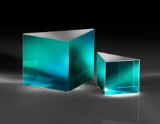
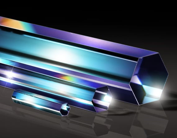
Les Prismes à Coins en N-BK7 peuvent être utilisés individuellement pour faire dévier un faisceau laser à un angle établi, ou deux prismes à coins peuvent être utilisés pour changer la direction d’un faisceau. La capacité d’un seul prisme à coins de dévier l’angle d’un faisceau incident est mesurée en Dioptres, avec 1 dioptre déviant le faisceau de 1 cm à une distance de travail de 1 m.
Deux Prismes à Coins peuvent être utilisés comme une paire anamorphique pour former un nouveau faisceau (pour corriger la forme elliptique des sorties diode par exemple). Une paire de Prismes à Coin peut également orienter un faisceau n’importe où sur un cercle décrit par l’angle complet 4xθ où θ est l’angle de déviation d’un seul prisme. Cette orientation du faisceau s’opère en faisant pivoter les deux Prismes à Coin sur eux-mêmes indépendamment l’un de l’autre. Ce qui est généralement utilisé pour balayer un faisceau à différents endroits pour des applications en imagerie.
Remarque : Le changement de direction d’un faisceau est indiqué en degrés et en dioptres. 1 dioptre correspond à une déviation de faisceau de 1 cm à une distance d’1 m du prisme.
Informations techniques
| N-BK7 | |
|
Typical transmission of a 3mm thick, uncoated N-BK7 window across the UV – NIR spectra. Click Here to Download Data |
|
|
Typical transmission of a 3mm thick N-BK7 window with MgF2 (400-700nm) coating at 0° AOI. The blue shaded region indicates the coating design wavelengh range, with the following specification: Ravg ≤ 1.75% @ 400 – 700nm (N-BK7) Data outside this range is not guaranteed and is for reference only. Click Here to Download Data |
|
|
Typical transmission of a 3mm thick N-BK7 window with VIS-EXT (350-700nm) coating at 0° AOI. The blue shaded region indicates the coating design wavelengh range, with the following specification: Ravg ≤ 0.5% @ 350 – 700nm Data outside this range is not guaranteed and is for reference only. Click Here to Download Data |
|
|
Typical transmission of a 3mm thick N-BK7 window with VIS-NIR (400-1000nm) coating at 0° AOI. The blue shaded region indicates the coating design wavelengh range, with the following specification: Rabs ≤ 0.25% @ 880nm Data outside this range is not guaranteed and is for reference only. Click Here to Download Data |
|
|
Typical transmission of a 3mm thick N-BK7 window with VIS 0° (425-675nm) coating at 0° AOI. The blue shaded region indicates the coating design wavelengh range, with the following specification: Ravg ≤ 0.4% @ 425 – 675nm Data outside this range is not guaranteed and is for reference only. Click Here to Download Data |
|
|
Typical transmission of a 3mm thick N-BK7 window with YAG-BBAR (500-1100nm) coating at 0° AOI. The blue shaded region indicates the coating design wavelengh range, with the following specification: Rabs ≤ 0.25% @ 532nm Data outside this range is not guaranteed and is for reference only. Click Here to Download Data |
|
|
Typical transmission of a 3mm thick N-BK7 window with NIR I (600 – 1050nm) coating at 0° AOI. The blue shaded region indicates the coating design wavelengh range, with the following specification: Ravg ≤ 0.5% @ 600 – 1050nm Data outside this range is not guaranteed and is for reference only. Click Here to Download Data |
|
|
Typical transmission of a 3mm thick N-BK7 window with NIR II (750 – 1550nm) coating at 0° AOI. The blue shaded region indicates the coating design wavelengh range, with the following specification: Rabs ≤ 1.5% @ 750 – 800nm Data outside this range is not guaranteed and is for reference only. Click Here to Download Data |
Reviews
There are no reviews yet.